Home
- POV-Ray Tutorial
Model Railroading
Railway Modelling
with POV-Ray
Index of Content
- Rail Track System
for POV-Ray
Basic Track Elements
- Straight & Curved
- Switches
- Wye + 3Ways
- Level Junctions
- Simplified Using by
RT_System_00.inc
- Rail Tracks Elements
with RT_System_00.inc
- Track Layout with
Model Scaled Tracks
- H0 Scale Tracks
- N Scale Tracks
- Z Scale Tracks
> Track Layout with
scaled Tracks
- Track Placement
- Tracks Up & Down
- Track Layout Examples
- Simple cyclic
- Simple eight
- Download of the
Rail Track System
|
Track Layout Technics with scaled Tracks
Demonstration with N scale track system of geometry type A:
Click here for download of the basic scene file RT_N_A111_BaseScene_0.pov for POV-Ray.
Preparations:
//-----------------------------------------------//
#include "transforms.inc"
//-------------------------
#declare Simulate_On =  0 ;  // -2, -1, 0, 1, 2, 3,
//  0=real tracks, 1=double rails, 2=symbolic blocks, 3=blocks+text
// -2=with gravel, -1 with base blocks (h = 0.20)
#include "RT_System/N_TypeA111/RT_N_TypeA111_Set_00.inc"
#include "RT_System/N_TypeA111/RT_N_TypeA111_Track_Up_00.inc"
// #declare N = 160; declared in set!
//-----------------------------------------------// |
The placement of curve track by the macro 'Rotate_Around_Trans' needs: #include "transforms.inc" !
The first include file contains all macros for a track set in N scale.
The linear base legth is the track called object{T_111}
with a real length of 111mm, here represented with a length of L111 = 0.111*N.
The switches / turnouts have an angle of 15 degrees and a curved track of radius R9 (~0.42887*N).
It declares also the variables 'N' (=160) and the 'Track_Distance' (~ 0.029 m *160)
The simulation type should be declared befor including the track set!
All tracks are starting at <0,0,0> in positive x direction.
The second include file contains a macro 'Track_Up_00("TRACKNAME", STEP, GRADIENT_TYPE)'.
This is prepared for easy simulating gradients in tracks up and
down as demonstrated later here.
|
|
Available Track Elements
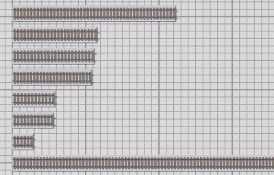
1) Straight Tracks
The standard straight track length is 'L111' (= 0.111 m *160),
the according track is 'object{T_111}'.
//-----------------------------------------------//
object{ T_222 rotate<0,0,0> translate<0*L222,0,0>}
object{ T_115 rotate<0,0,0> translate<0*L111,0,0>}
object{ T_111 rotate<0,0,0> translate<0*L111,0,0>}
object{ T_107 rotate<0,0,0> translate<0*L107,0,0>}
object{ T_057 rotate<0,0,0> translate<0*L057,0,0>}
object{ T_055 rotate<0,0,0> translate<0*L055,0,0>}
object{ T_028 rotate<0,0,0> translate<0*L028,0,0>}
object{ T_777 rotate<0,0,0> translate<0*L777,0,0>}
// lenght free:
object{ T_Straight(0.331*N) translate<0.331*N,0,0>}
//-----------------------------------------------// |
|
Straight Tracks
|
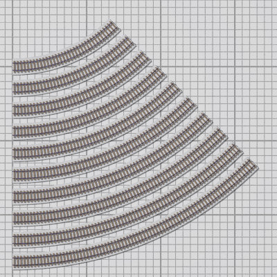
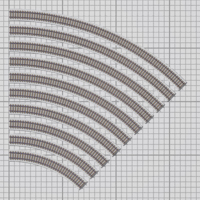
2) Curve Tracks
There is a big bunch of curves with the radii between R1 (~ 0.195 m * N)
over R9 ( ~ 0.429 m * N = switch radius) to R10 ( ~ 0.468 m * N ) to keep the layout as flexible as possible.
Producers of model tracks don't produce all these radii - so it's up to you to select the according radii.
Other radii can be realisized by flexible tracks.
For easier design of layouts there are also defined curves to the right i.e. 'object{T_R1_45}' and curves to the left
i.e. 'object{T_R1_45}'
//-----------------------------------------------//
object{ T_R1_45
        Rotate_Around_Trans(<0,0*45,0>,<0,0,-R1>)}
object{ T_R2_45
        Rotate_Around_Trans(<0,0*45,0>,<0,0,-R2>)}
object{ T_R3_45
        Rotate_Around_Trans(<0,0*45,0>,<0,0,-R3>)}
 // ... etc, etc, ... //
object{ T_R9_45
        Rotate_Around_Trans(<0,0*45,0>,<0,0,-R9>)}
object{ T_R10_45
        Rotate_Around_Trans(<0,0*45,0>,<0,0,-R10>)}

object{ T_R1_30
        Rotate_Around_Trans(<0,0*30,0>,<0,0,-R1>)}
object{ T_R2_30
        Rotate_Around_Trans(<0,0*30,0>,<0,0,-R2>)}
 // ...
object{ T_R1_15
        Rotate_Around_Trans(<0,0*15,0>,<0,0,-R1>)}
 // ...
object{ T_R1_075
      Rotate_Around_Trans(<0,0*0.75,0>,<0,0,-R1>)}
// radius and angle free:
object{ T_Curve( 0.250*N, 17.5 )
    Rotate_Around_Trans(<0,17.5,0>,<0,0,-0.250*N>)}
//-----------------------------------------------// |
Note: Because of preview with track names we should avoid any mirroring
of curves, switches etc., otherwise with mode 'Simulate_On = 3'
we will see only mirrored textes!
This means: Don't use 'scale<-1,1,1>' or 'scale<1,1,-1>
|
Curve tracks T_L1_45, T_L2_45, ..., T_L10_45
Curve tracks T_R1_45, T_R2_45, ..., T_R10_45
|
3) Turnouts / Switches
and Level Junctions / Diamond Crossings
For turnouts / switches we need to declare the according switch direction.
Turnouts / switches: angle 15°, radius R9, straight length L111
The level junctions / diamond crossings are available
Asymmetrical: 15° (X15_RL, X15_LR: main L111, diagonal L115)
Symmetrical: 30° (XX30: length L115, XX30s: lenght ~ 0.05 m*N).
//switch directions: ----------------------------//
#declare SD1= 0;// 0=straight, 2=curved
#declare SD2= 0;//-1=left, 0=straight, 2=right
#declare SD3= 0;//-1=left, 1=right
// turnouts - switches
object{ SW_R(SD1) rotate<0,0,0> translate<0*L111,0,0>}
object{ SW_L(SD1) rotate<0,0,0> translate<0*L111,0,0>}
object{ SW3(SD2)  rotate<0,0,0> translate<0*L111,0,0>}
object{ SWY(SD3)  rotate<0,0,0> translate<0*L111,0,0>}
// level junctions - diamond crossings
object{ X15_RL    rotate<0,0,0> translate<0*L110,0,0>}
object{ X15_LR    rotate<0,0,0> translate<0*L110,0,0>}
object{ X30    rotate<0,0*15,0> translate<0*L115,0,0>}
object{ X30s   rotate<0,0*15,0> translate<0*L115,0,0>}
//-----------------------------------------------// |
|
Turnouts / Switches and
Level Junctions / Diamond Crossings
|
4) Improvised Double Slip
//-------------------------------------------//
object{ XX_RL  rotate<0,0,0> translate<0*L110,0,0>}
object{ XX_LR  rotate<0,0,0> translate<0*L110,0,0>}
//-------------------------------------------// |
Note: These double slips are only available in improvised versions -
no switch directions to choose!
|
Improvised Double Slip
|
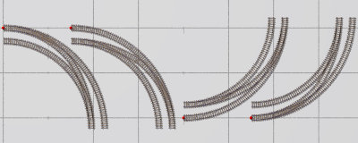
5) Improvised Curve Switch Sets
//-------------------------------------------//
object{ CSW12_R rotate<0,0,0>
        Rotate_Around_Trans(<0,0*45,0>,<0,0,-R2>)}
object{ CSW21_R rotate<0,0,0>
        Rotate_Around_Trans(<0,0*45,0>,<0,0,-R2>)}

object{ CSW12_L rotate<0,0,0>
        Rotate_Around_Trans(<0,0*45,0>,<0,0,-R2>)}
object{ CSW21_L rotate<0,0,0>
        Rotate_Around_Trans(<0,0*45,0>,<0,0,-R2>)}

//-------------------------------------------// |
Note: These curve switches are only available in improvised versions -
no switch directions to choose!
|
Improvised Curve Switch Sets
CSW21_R, CSW12_R, CSW12_L, CSW21_L
|
|


